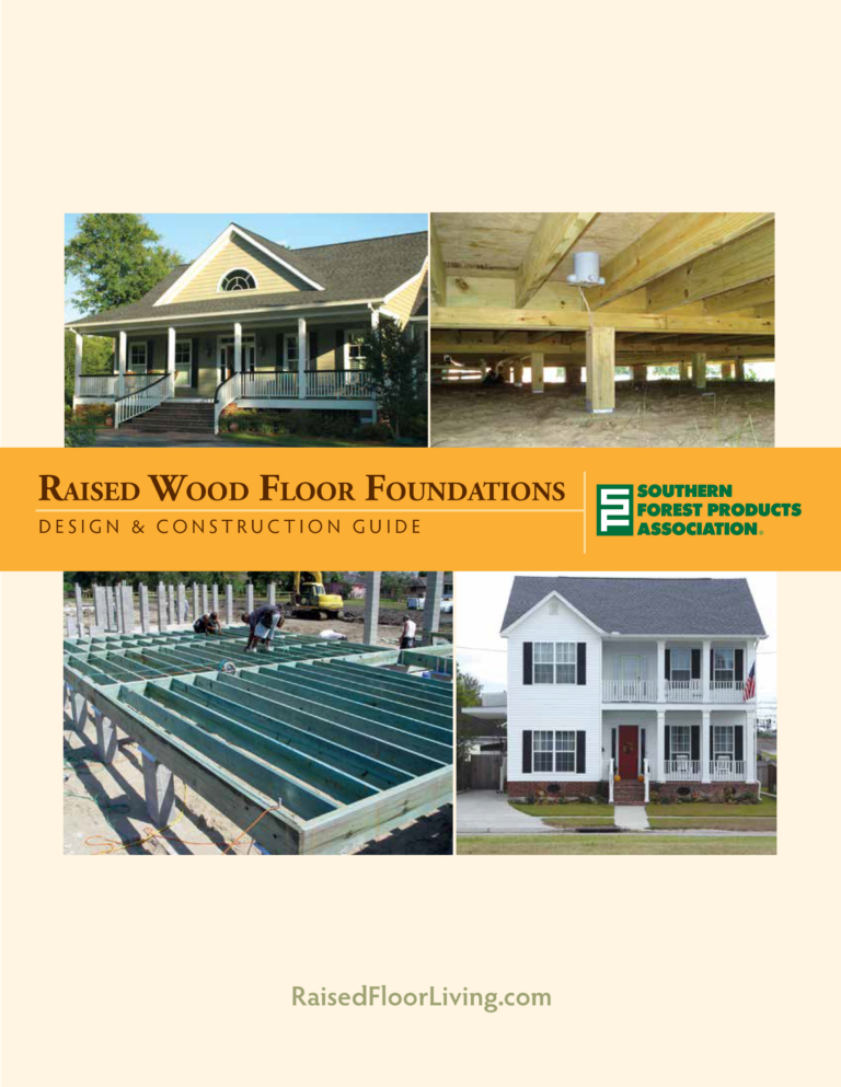
Pier-and-beam foundations offer a high level of versatility, specific not only to the dead, live, seismic and wind loads to be supported and/or restrained, but also to the girders or sill beams and floor joists and their respective span capabilities.
Exterior Wood Piling
Pressure-treated wood piles are a common foundation for homes built in beachfront locations, as well as in other areas where soils have minimal bearing capacity. The cross-section area of a pile has little to do with its bearing capacity. The actual bearing support of the pile is the surface friction of the sand or soil encapsulating the pile below grade.
In beachfront construction, the length of the pile below finished grade is typically the same length as the pile above grade, or longer. In other pile applications, the length of the pile below grade may be several times the length of the exposed pile – subject to the soil properties providing friction support.
Anchoring girders to piles is a simple process with appropriately sized bolts connecting the assembly to resist loads. Cantilevered floor joist systems are
sometimes preferred in conjunction with this type of foundation in order to allow tolerance for pile placement.
In coastal areas, fasteners should be a minimum of hot-dip galvanized G185 or stainless steel.
NOTE: Specification of the proper preservative retention level is important for pressure-treated wood components of a foundation – piling, posts, sill plates and framing (where required).
Perimeter Masonry Pier on Grade Beam
Where the stability and bearing capacity of the soils are sufficient to support loads, open crawlspace foundations are typically built with masonry piers on continuous grade beams or footings. The continuous footing “ties” the foundation together, resisting any lateral movement from the bearing soils, while providing support for individual piers distributed over a larger area compared with spot footings.
Where piers are required to resist lateral loads or uplift, such as those supporting exterior shear walls, the masonry piers must be designed accordingly, typically reinforced with vertical steel rods (rebar) and concrete fill. Anchors or straps to resist uplift are “wet-set” into the piers, secured by the concrete fill.
The specification of masonry piers provides for precise placement – eliminating the need for cantilevered floor joist systems – allowing exterior wall sheathing panels to be installed continuous over wall frames above to the floor girders.
Masonry piers on continuous concrete footings may also be used in conjunction with other materials to enclose the crawlspace, and should not be considered as an option for use only with open crawlspace construction.
Interior Masonry Pier on Spot Footing
Where soil bearing of sufficient capacity and stability exists, spot footings are often more cost efficient than continuous footings.
Masonry piers placed on spot footings to support floorframe systems at the interior of the structure are typically not subject to either lateral or uplift loads, and therefore may not require the same reinforcement as those at the exterior perimeter, subject to pier height.
Straps or anchors that provide stability throughout floorframe construction will typically require only concrete fill in a single CMU column, facilitating the connection of anchors or straps within the pier. Where straps may be wet-set into the spot footing prior to the construction of the piers, no concrete fill would be required, again subject to the height of the pier.
Interior Concrete Pier on Bell Footing
Poured-in-place concrete piers are the choice of some designers and builders. They may be formed and poured separately from concrete footings, but with careful planning they may be poured at the same time as footings, reducing the number of required inspections and overall construction time.
When poured with the required sized pier, it is typical for the footing to be of much greater cross-section area than the column itself – requiring the column to “flare” or “bell” at its base – normally below the finished grade.
Cylindrical cardboard tubes are often used as forms for round columns; square columns may use temporary forms or purpose specific reusable forms. In either case, when poured-in-place concrete columns are specified and poured at the same time as the required spot footing, the resulting bell shape of the flared column base below undisturbed finished grade can provide enhanced uplift resistance for the structure.
Interior Wood Post on Spot Footing
Another option for piers on either continuous or spot footings is the specification of wood posts. Pressure-treated wood posts, including solid lumber such as 6x6s, or multiple plies of dimension lumber, may be installed on appropriate post anchor bases and attached to the top of the footing or wet-set into the footing.
At the connection to the footing, the post anchor base must resist lateral, shear and uplift loads, as required. At interior wood post piers, connections at the top of the footing may also be required to resist lateral, shear and uplift loads from the structure above. For piers along the perimeter, bracing of the posts to resist such loads will be required.
Where wood post piers are not required to resist lateral or shear loads from the supported structure above – as may be the case with interior piers of the structure – additional bracing of posts should not be required.
Some builders prefer to wet-set pressure-treated wood posts into appropriately sized concrete spot footings. Uplift resistance can be provided through insertion of reinforcement bars or bolts into the post prior to pouring concrete. In such cases, the recommendation is made to take appropriate steps to prevent surface water penetration into any cavity between the concrete spot footing and the wood post that may be created by shrinkage of the post over time.